
Industry insightPublished: · By MorZan
How Does a VFD Work? Rectifier, DC Bus and IGBT Inverter Explained
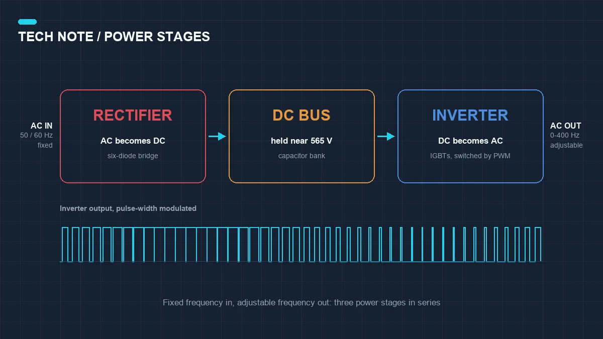
A VFD works by breaking one job into three stages. Mains power arrives at a fixed 50 Hz or 60 Hz, and the motor needs something adjustable. So the drive first converts AC into DC, holds that DC steady, then rebuilds AC at the frequency and voltage it wants. Rectifier, DC bus, inverter. Everything else on the board exists to control those three stages.
The rectifier is the first stage. Its job is to turn incoming AC into DC, and in most general-purpose drives it is a bridge of six diodes. A diode conducts in one direction only, so each pair lines up with a phase and the output becomes a pulsing DC. That DC is not smooth yet, but its polarity is now fixed, and that is the point.
Larger drives, and any drive that needs to send power back to the grid, replace the diodes with thyristors or with an active front end built from IGBTs. The rectifier then becomes something the control board can regulate.
The DC bus is the second stage, and it is mostly a bank of capacitors. Its job is to hold the rectified voltage steady while the inverter draws current in short, sharp pulses. With too little capacitance the bus voltage sags on every switching event, and the drive trips on undervoltage.
Bus voltage follows the supply. A 400 V supply gives roughly 565 V DC, and a 480 V supply gives around 650 V DC. That number matters, because it sets the ceiling on the output voltage the inverter can produce.
The inverter is the third stage. It takes the steady DC and switches it back into three-phase AC using IGBTs, with one pair for each output phase. Every IGBT is either fully on or fully off, and the drive decides when each one switches. Control that timing and you control both the frequency and the voltage at the output.
This is where PWM comes in. The IGBTs do not switch at the output frequency. They switch at a much higher carrier frequency, usually somewhere between 2 kHz and 16 kHz, and the output frequency is built from the width of the pulses rather than from how often they appear.
Widen the pulses and the average voltage rises. Narrow them and it falls. How many pulses go into one cycle of the output is what sets the output frequency. The motor winding is an inductor, and it smooths that pulse train into something close to a sine wave. Put a scope on the terminals and you will see a switched, square-edged voltage, while the current in the windings stays almost sinusoidal.
Frequency and voltage have to move together. The magnetic flux in an induction motor is proportional to voltage divided by frequency, so halving the frequency at full voltage doubles the flux. The iron saturates, the magnetising current climbs, and the winding overheats. A drive therefore reduces the V/f ratio as it reduces speed, keeping the two in step.
At very low frequencies the stator resistance starts to eat into the available torque, so most drives add an adjustable voltage boost below about 5 Hz. That one setting decides whether a loaded conveyor or a positive-displacement pump will start at all.
What issues the commands is the control layer, and it comes in different depths. Open-loop V/f is the simplest scheme and it covers pumps and fans well enough. Adding encoder feedback, or using sensorless vector control, lets the drive hold torque and speed much more tightly, which is what conveyors, extruders and winders need when the load changes quickly. Which scheme suits a given duty is a subject in its own right.
Power can also flow backwards. When a motor decelerates a high-inertia load, or a pump runs downhill, the motor turns into a generator and pushes energy back into the DC bus. Bus voltage rises, and the drive has to deal with it, either by switching a braking resistor across the bus or by returning the energy to the supply through an active front end. An overvoltage trip during a stop is often this problem and nothing else.
Put the whole path together. Three-phase power enters the rectifier at 50 Hz and leaves it as DC. The bus holds that near 565 V. The inverter switches it into a three-phase output at, say, 32 Hz for a pump that needs half speed. The motor turns at roughly two thirds of its rated speed and draws far less power than the same pump would on a throttling valve. Nothing is burned off in a resistor and nothing is throttled away in a valve. Speed itself is the control.
This picture rules out a few common misunderstandings. A VFD does not slow a motor by lowering voltage alone, because the frequency has to come down with it or the iron saturates. It is not a soft starter with a display, because a soft starter ramps the voltage up once and then hands the motor straight to the mains. And it does not save energy in every application. On a constant-torque load running at full speed there is very little to save. The savings come from loads where flow or pressure follows the speed, which is why pumps and fans make up most of the installed base.
Once the three stages make sense, the practical question is which drive to put on a given motor. The workhorse in most plants is the low voltage VFD in the 380 to 480 V range, covering pumps, fans and conveyors. A general-purpose model carries both V/f and sensorless vector control in the same unit, along with a built-in PID loop for constant pressure or constant flow. If you are specifying for a known duty, send us the motor nameplate and the operating conditions, and we usually confirm the model and its parameters within 24 hours.
VFD Applications
Every variable frequency drive (VFD) application is different, because every load behaves differently. These guides explain the drive features that matter for your industry and link to the recommended product range.
All industry guides