
Industry insightPublished: · By MorZan
VFD for a Water Pump Station, From an Italian Email to a Power Bill
An email from Italy about a VFD for a water pump station
The email arrived at 9:40 in the evening.
I was about to shut the laptop. A notification blinked in the corner. The subject line was in Italian. I recognised inverter and pompe, and guessed that the rest, Richiesta informazioni, meant a request for information. Four lines of text, three photos attached.
The sender was Marco Bellini, writing from Ceramiche Valle. The address was a small town north of Sassuolo. A tile factory.
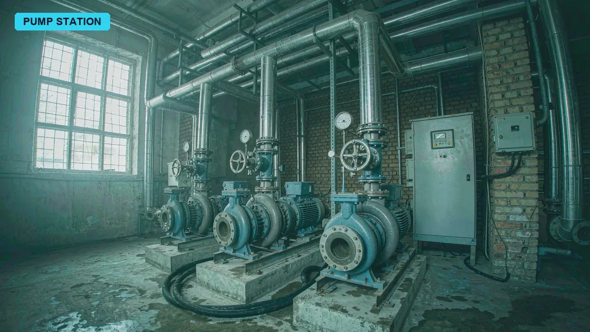
The first photo was the pump room, shot against the light, three pumps blurred into one shape. The second was a nameplate, half rusted, the power rating on exactly the part that had gone illegible. The third was inside the control cabinet, the door open, a layer of dust over everything, two contactors burnt black.
One sentence in the body I did understand. Perché le pompe partono e si fermano continuamente. The pumps keep starting and stopping.
That night I sent back a short reply, three sentences. I need the nameplate, the cabinet wiring, and last month's electricity bill.
It went out at 10:05 my time, 4:05 in the afternoon in Italy.
Diagnosing a pump station 7,000 km away, and why I did not start with specs
Marco answered at 6:30 the next morning.
He photographed all three things I asked for. None of them was usable. The nameplate was the same rusted plate from a different angle. The cabinet was there, but there were too many wires to tell which went in and which came out. The bill was shot at an angle, and only the total was in frame.
Anyone who sells abroad knows this. Ask a customer to describe something and he leaves things out. Ask him to photograph it and he photographs the wrong thing. At 7,000 km, all you can do is ask again.
I drew him a diagram, photographed it with my phone and sent it over. Three spots marked. The face of the nameplate, the terminal strip in the cabinet, the readout on the meter. Next to each one, a short line of English and a red circle.
On the third day the photos finally came back right.
The nameplate read 45 kW, 400V, 50Hz, four pole, IE3. Three pumps, same model, built two years apart. The cabinet was star-delta starting, two contactors and a timer relay, no soft starter, no drive. The meter was a three-phase electronic unit that could page through accumulated active energy.
That evening we had our first video call. He walked through the pump room holding the phone, the picture shaking, water noise and pump hum in the background.
He stopped in front of the second pump and put the phone close to the motor. I do not speak Italian. He switched to English, short words only. Pressure, start, stop, noise. One word he said three times before I caught it. Aspiration. He meant suction. In Italian the suction inlet is aspirazione, and the translation app had given him aspiration.
That was the word I wanted. If the suction side has a problem, the pump cavitates, and of course the pressure is unstable.
I asked Marco to point the phone at the suction pipe and walk two metres upstream. He took a few steps and a strainer came into frame, a Y type, with a layer of white scale on the outside of the screen.
At that moment I was about seventy percent sure. The unstable pressure might not be the pump's fault at all.
Day shift and night shift in a ceramic plant, and how they forced the pumps to cycle
Marco later sent a video he shot at the seven o'clock shift change.
Two production lines, he said. Day shift starts at six, both lines running. At six in the evening one line stops and only one runs through the night. Spraying, glaze line washing, equipment cooling, all of it draws water from this pump station.
Day shift uses a lot of water. Two pumps run together and the pressure just about holds. At night demand drops to a third, and the two pumps still work the old way, loading and unloading. Pressure reaches 7 bar and they stop. It falls to 5.5 and they start again.
Dozens of starts a night.
I asked him to count them. He said he never had, but the contactors clicked a lot every day and the shift crew was used to it. He sent a recording, phone placed next to the cabinet. In thirty seconds I heard four pulls.
That is the problem. The pumps were sized for the day shift peak, and at night they were still working the same way. Nobody thought it was wrong, because the machines kept turning and the gauge kept moving.
I did the arithmetic. Three pumps, two duty and one standby, 45 kW each. The customer's electrician had clamped 71 A on a running pump. With a power factor of 0.86, input power is 1.732 times 400 times 71 times 0.86, which comes to 42.3 kW, call it 42.
Day shift, two pumps, 84 kW. Night shift, one pump running intermittently, on roughly forty-five percent of the time.
I wrote that number in my notebook. Every energy saving figure later came out of it.
Three pumps, two running and one standby, deciding whether this water pump station was worth a VFD retrofit
Not every water pump station should have a VFD. I ran it through three checks first.
Three disqualifiers you can judge from photos
Motor insulation below five megohms
The most common trap in old pump stations. If the winding is damp or the insulation has aged, the drive's high frequency pulses will punch through it. The pump survives, the motor burns. I asked Marco to have a local electrician megger the motors. All three read above 20 megohms, so that one passed.
Cavitation or a leaking mechanical seal
Cavitation sounds like beans frying inside the casing. A leaking seal leaves a puddle under the pump base. In Marco's video there was a water mark under the second pump, but it was a drip, not a spray. I passed that one with a condition. Wash the Y strainer first, then see whether it still leaks.
Heavy throttling in the network
Some plants hold the discharge valve half closed just to control pressure. Those systems gain the most from a drive, but they also hide the real problem best. I asked Marco for the valve position. He sent a photo, stem fully up, wide open. That told me something useful. They were not throttling to control pressure. They were fighting it with start and stop.
Three checks done. The job was worth doing.
But I did not quote yet. I wrote to him first, and put one sentence at the front. If that strainer stays clogged, the pressure will still be unstable after the drives go in, and at that point it will not be the drive's fault.
He replied okay. Attached was a photo of a cleaned strainer.
I sized the savings with the affinity laws, and I got it wrong
This one was my mistake, and it needs to be written down properly.
For pump savings, the textbooks give you a beautiful rule called the affinity laws. Flow is proportional to speed. Head is proportional to the square of speed. Shaft power is proportional to the cube of speed.
I applied it straight.
Day shift demand is 140 m³/h, split between two pumps, so 70 each. That is seventy percent of rated flow. Seventy percent cubed is 0.343. 42 times 0.343 is 14.4 kW, and two pumps make 28.8 kW.
Instead of 84 kW, 28.8 kW. A saving of sixty-five percent.
I put that energy saving figure in the quotation email and drew a curve to go with it.
Marco wrote back the next day. He said the number was so good he did not dare believe it. He asked whether we had left something out.
He was right to ask.
Recomputing with static head, and the water pump VFD energy savings halved
I went through it again, and the problem was a parameter I had never asked for.
This water pump station does not move water from one low level to another. It lifts water to a tank on the north side of the plant, on a platform twelve metres up. Add the pipe losses and the static head is about fifteen metres.
Static head means that no matter how small the flow gets, those fifteen metres still have to be overcome. The pump cannot stop, and the speed cannot drop all the way down.
So the duty point does not just slide along the affinity curve. You have to solve two equations together.
I simplified the pump curve into a parabola. Shutoff head about 55 m, rated point 48 m at 100 m³/h. Written out, H equals 55 minus 0.0007 times flow squared.
The system curve is static head plus friction. H equals 15 plus 0.0033 times flow squared.
Where the two lines cross is where the pump actually runs.
Speed ratio is not flow ratio
This is the step people get wrong.
When demand falls to 70 m³/h, the speed ratio is not 0.7. It is 0.793. Flow dropped, but the head still has to sit around 31 m, and if the speed comes down too far the pump cannot hold it.
Here is how it works out.
Put 70 into both curves. 55 times the speed ratio squared, minus 15, equals 0.004 times 4,900. So the speed ratio squared is 0.629, and its square root is 0.793.
Power follows the cube. 42 times 0.793 cubed is 20.9 kW.
Two pumps, 41.8 kW. Against 84 kW, that is a fifty percent saving. Not sixty-five.
At night, 45 m³/h, speed ratio 0.648, 11.4 kW per pump. The old night figure was one pump running intermittently, 18.9 kW on average, so that is a forty percent saving.
Over a day, the old arrangement was twelve hours at 84 kW plus four hours at 18.9 kW, which is 1,083.6 kWh. After the retrofit, twelve hours at 42 kW plus four at 11.4 kW, which is 549.6 kWh.
534 kWh a day, a saving of forty-nine percent.
At 250 working days a year, annual consumption falls from 270,900 kWh to 137,400, a saving of 133,500 kWh.
Marco's tariff was 0.21 euro per kWh, taxes and system charges included. 133,500 times 0.21 is 28,000 euro.
I sent the revised version with one line at the top. My previous figure was wrong, I used a formula that did not apply here. Please use this version.
He answered quickly. He said he believed this number.
Two VFD panels and a pressure loop, what you should not cut from the quote
The three items on the quote you cannot drop
The quote had three blocks.
The first was two 45 kW drive panels. Why not three. Because two pumps run and one stands by, and the standby only gets switched over by hand during maintenance. Fitting a drive to the standby means paying for a cabinet that sits unpowered most of the year. I explained this to Marco twice. He wanted all three at first, saying they might run three together later.
I did the sum for him. Three pumps at once need 210 m³/h of demand. Their record was 160. The extra money was better spent elsewhere.
The second block was the pressure loop hardware. A 0 to 10 bar transmitter, a screened cable, and a PID module inside the panel. It looks like small change. It is the part that decides whether the whole retrofit works. Going from fixed speed to variable speed is not really about swapping cabinets. It is about turning pressure from a switch into a continuous signal. That is what a constant pressure water supply actually is, and the cabinets are the easy half.
The third block was the CE documentation and EMC filters. That deserves its own section.
One line on the quote was deliberately left blank. Installation and on-site commissioning by the customer. The note said why. Our people would not be there, and we could not carry responsibility for local construction work. Marco said they had a regular electrician and he was fine with that.
One panel or all three, Marco went back and forth for three weeks
The proposal went over, and then nothing for three weeks.
I followed up once. He said he was waiting for the owner to sign. I asked again later. He said the owner was working out the payback.
Eventually he told me the truth. Someone at the plant had suggested fitting one drive first, and adding the second if it worked.
Why one VFD and one fixed-speed pump do not work together
It sounds like the cautious option. It does not hold up. Two pumps running in parallel, one on a drive and one at fixed speed, do not match. The fixed-speed pump always runs flat out, and the drive is forced to keep backing off until the fixed-speed unit carries the load and the drive is just along for the ride. The only case you can test that way is single pump operation, which means the night shift.
I drew him a chart, two lines. One showed how power splits when both pumps have drives. The other showed one drive and one fixed speed. On the second line the drive sits almost at minimum speed, its power will not come down, and running at low frequency for long periods makes its efficiency worse.
He looked at it and said this was not what they had assumed.
In the end the owner decided, and both pumps were converted. He signed on the fifth of June.
CE marking for Italy, and why 400V is not 380V
A drive sold into the EU has to meet two directives, electromagnetic compatibility and low voltage. On the product that means the CE mark, a declaration of conformity, and test reports.
Their electrical consultant asked about it in his very first email. Did we have an EN 61800-3 report, category C2.
C2 is the second environment, which covers residential areas, and its conducted emission limits are tighter than C3 for industrial areas. Marco's water pump station sits in an industrial zone, so C3 should have been enough. The consultant insisted on C2 because the station is eight metres from the perimeter wall, and beyond that wall are houses.
I did not argue. One more filter stage costs money, but it removes the risk of a complaint later.
Where 400V differs from the 380V we use at home
The voltage level is different. Low voltage three phase in China is 380V. In the EU it is 400V, and both run at 50Hz. Twenty volts does not sound like much. It matters in a few places.
First, the drive's rated output voltage has to be selected for 400V, not 380V. A 380V unit on a 400V network runs a higher DC bus voltage, and that is hard on the capacitors over time.
Second, the motor connection. A 45 kW IE3 motor at 400V is usually delta connected. The same rating in China is often star. The customer has to confirm this on site. Connect it wrong and you lose torque at best, and burn the winding at worst.
Third, the earthing system. Italy commonly uses TT, with 30 mA residual current protection at the incoming supply. A drive leaks current by design, and with filters fitted it leaks more, which trips that protection for no good reason. My advice to Marco was to change the device to type A or type B, set the trip current at 300 mA, and add a time delay.
Those three points went into the technical agreement, eleven pages in all.
The crate stuck in Genoa, and August shutdown across Italy
We shipped on the twentieth of June. Two cabinets and accessories, in two wooden crates.
Crates need fumigation and IPPC marks. We have done that many times and it does not go wrong. What went wrong this time was the shipping marks.
The delivery address the customer gave was their factory. The forwarder put a warehouse in Milan on the bill of lading. The two did not match. When the goods reached Genoa, the customs broker said the marks and the bill of lading did not agree, and the customer would have to issue a statement.
Marco's side was about to hit August.
Italy takes August off. It is national, it is called Ferragosto, it starts in mid August, and plenty of plants stay closed to the end of the month. I read Marco's auto reply three times. The first was in Italian, the second in English, the third he had typed himself, saying he was at the seaside, the signal was poor, and urgent matters should go to someone else.
For three weeks I could do nothing.
The goods sat in port and storage charges ran every day. I pushed the forwarder. The forwarder pushed the broker. The broker needed the customer's signature, and the customer was at the beach.
It was settled on the twenty-sixth of August. Marco signed the statement on his first day back.
Since then, anything we ship to Europe gets its marks checked against the bill of lading three times before it leaves, and we ask the customer when their holiday is.
The electrician swapped two phases, and the sound a pump makes when it runs backwards
The panels reached the plant on the second of September and the customer started installing.
Marco's electrician was named Rossi, twenty odd years in the trade, a confident man. He wired to our drawing. On the third day he messaged me. After power on the pump moved no water, and the sound was wrong.
I told him to isolate first, then photograph the motor terminal box.
The photo came. One look was enough. U and V were swapped.
Reverse two phases on the drive output and a three-phase motor runs backwards. That does not damage an induction motor. But a centrifugal pump running backwards moves no water, and the check valve gets pushed shut against the flow with a heavy clunk.
Rossi was not convinced. He said the colours in our drawing did not match the wires in his hand. He was right about that. Our drawing follows IEC colours, brown black grey. The wiring on site had been replaced at some point and the colours meant nothing.
That taught me something. An export drawing cannot rely on colour. It has to carry terminal numbers, and it has to tell the customer that the numbers rule and the colours are only a guide.
I drew a new one, marking every wire U1 V1 W1 inside red circles, then recorded a forty second video with my phone, pointing at a terminal strip on my desk.
Rossi wired it again after watching the video. The pump moved water.
He told Marco afterwards that these Chinese people were quite thorough.
First night of remote commissioning, and a pressure curve like a saw blade
The first proper commissioning session was the evening of the eighth of September. Three in the afternoon in Italy, nine at night here.
Video connected. Marco stood in front of the cabinet holding the phone, Rossi working beside him. I asked for the setpoint at 5.8 bar, proportional band at 30 percent, integral time at 8 seconds.
The pump started. Pressure climbed, overshot to 6.4 bar, fell to 5.1, climbed again.
The curve looked like a saw blade.
My first thought was the PID settings. I widened the band to 50 percent and stretched the integral time to 15 seconds. It improved slightly. It still oscillated, just more slowly.
The transmitter was in the wrong place, and no PID setting would fix it
After forty minutes of this I asked Marco to point the phone at the transmitter.
There it was. The transmitter sat a metre and a half from the pump discharge, directly behind the check valve.
Flow at that point is turbulent. Every time the pump turns, the local pressure spikes, the transmitter reports that spike as system pressure, the drive slows down, pressure drops, and it speeds up again.
With the sensor that close, the PID was chasing a signal that was not real, no matter how it was tuned.
I asked him to move the transmitter to the header, at least five metres from the discharge, ideally next to the pressure vessel. Rossi said that meant drilling a new tapping and shutting the water off for half a day.
We did not finish that night. I closed the call at 11:30 my time, 5:30 in the afternoon there. He said he was going to get dinner.
The next day he moved it. We reconnected. The curve flattened, holding within plus or minus 0.15 bar.
There was still a problem.
Around 42 Hz there was an audible resonance in the pipework, and the discharge line shook on its brackets. The pipe's natural frequency was meeting the pump's excitation frequency.
The fix is simple. Set a skip frequency and jump the 40 to 44 Hz band. The cost is that the pump cannot sit in that range, so it has to pass through quickly.
After that the resonance went away.
We finished at six in the afternoon Italian time, midnight here. Marco gave me a thumbs up on the screen. In the background the pumps already sounded flat and even.
That is what steady pressure sounds like. Not a gauge that keeps moving, just a pump running at one speed and staying there.
Three months later he sent the power bills, 7% below my estimate
On the nineteenth of December Marco sent an email with two bills attached.
One covered September to December 2025, the other the same period in 2026. Output was about the same, he said, and the station had held constant pressure since we finished. Two lines on days, one at night.
The 2025 period used 67,800 kWh. The 2026 period, 34,900.
A saving of 32,900 kWh.
Annualised, that is 131,600 kWh. My estimate was 133,500, less than two thousand apart.
The result was good enough that I did not quite trust it.
I asked him to photograph both bills clearly and exported the daily run logs for a look. Then I understood. That comparison could not be used as it stood.
Three reasons.
The missing seven percent, three reasons
First, this September to December was cooler than the year before, and the night shift used less water. Less water means lower speed, which saves energy on its own. That part is not the retrofit's credit.
Second, Rossi switched the drive back to fixed frequency for eleven days in October. His reason was that nobody watches the station at night and he was worried about a failure. Eleven days at full power ate into the savings.
Third, Marco raised the setpoint from 5.8 bar to 6.2. He said higher pressure made the workshop happier. Four tenths of a bar is one more step of pump speed, and power follows.
Strip those three out and the real annual saving is around 124,000 kWh.
Against my 133,500, that is 9,500 short, seven percent.
124,000 times 0.21 euro is 26,000 euro a year.
Equipment and sea freight came to 21,000 euro. Payback just over nine months.
This remote diagnosis process is now on our export checklist
After this job I changed three things.
The first was the enquiry form. We used to ask customers for parameters and take whatever came back. Now the first field is static head. Without that number, any savings promise is a guess. If I cannot get static head, I would rather not quote.
The second was the wiring drawing template. Colours are gone, terminal numbers only, plus one extra page saying that site wiring colours may not match the drawing and that terminal numbers take precedence.
The third was a three way check before shipment. Marks against the bill of lading, bill of lading against the invoice, invoice against the customer's address. Three passes, plus one question about when the customer takes their holiday.
Those three now sit on our export checklist, and every project goes through them.
Looking back, the biggest problem on this job was not technical. It was that I wanted to hand him a good number too badly. The affinity law curve was so clean that I never asked about static head. If Marco had not written back with that question, whether we had left something out, the panels would have gone in and the first power bill would have shown the gap.
By then it would have been too late to explain.
For the record, plant name, location, people's names and some operating data have been changed to protect the customer. The method and the reasoning are unchanged, and every figure above can be recomputed with your own numbers.
VFD Applications
Every variable frequency drive (VFD) application is different, because every load behaves differently. These guides explain the drive features that matter for your industry and link to the recommended product range.
All industry guides