
Industry insightPublished: · By MorZan
VFD Harmonics and THD: What They Are and How to Reduce Them
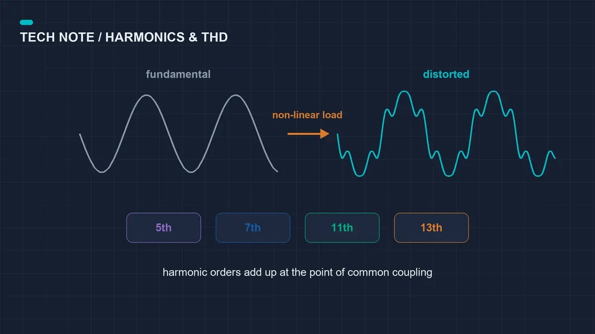
A variable frequency drive does not draw a smooth sine wave. It rectifies the incoming supply into a DC bus and pulls current in short pulses near the voltage peaks. Those pulses add harmonic currents at the 5th, 7th, 11th and 13th order. The consequence is not a problem inside the drive: it is a distorted voltage waveform shared by every other load on the same transformer. Transformers run hotter, capacitor banks age early, and sensitive electronics on neighbouring panels can trip without an obvious cause.
The figure that matters is total harmonic distortion at the point of common coupling (PCC), not at the drive terminals. On a stiff supply a small drive can measure 40% current distortion at its own input terminals and still leave the PCC inside a 5% voltage THD limit. Conversely, a large drive on a weak transformer can look acceptable at the terminals and push the whole plant out of compliance. Before accepting any mitigation quotation, ask for the short-circuit ratio of the site and the harmonic standard the utility enforces.
Mitigation scales with cost. A DC link reactor is the cheapest first step and typically removes a large share of current distortion with no extra panel space. An AC line reactor adds supply impedance and protects the rectifier on weak grids or where the transformer is shared. A 12-pulse or 18-pulse rectifier with a phase-shifting transformer is the robust answer for large drives on a shared supply, at a real cost in footprint and price. Specify the limit first, measure the baseline second, then buy the lowest-cost option that satisfies both.
VFD Applications
Every variable frequency drive (VFD) application is different, because every load behaves differently. These guides explain the drive features that matter for your industry and link to the recommended product range.
All industry guides