
Project location: Shaoxing, Zhejiang, China · By MorZan
Commissioning a Linear Motor Pumping Unit: Replacing the Beam Pump's Gearbox and Crank
- Plant / customer:
- Oil extraction equipment builder
- Published:
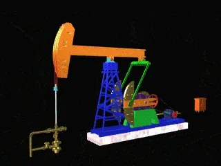
The beam pumping unit — the nodding horsehead seen across every oilfield — turns rotary motion into the up-and-down stroke of a downhole pump. A motor turns, a gearbox reduces the speed, and a crank-and-connecting-rod mechanism converts the rotation into vertical movement of the horsehead. The horsehead lifts and lowers a polished rod and a sucker-rod string, which in turn works the plunger of the downhole pump and raises crude to surface. The motion is reliable and the mechanism is decades old.
Its weaknesses are equally well known. Every energy conversion through the gearbox and the crank linkage costs something, and the mechanism is built for the heaviest well on the field, so a well that produces less runs a large machine at part load — the classic big-machine-small-load penalty. Typical overall efficiency on a beam unit is quoted at around 25 %. There is a second, less obvious loss: on the downstroke the pumping unit drives the motor, so the motor generates, and that energy has to be absorbed by a braking resistor where it becomes heat.
A linear motor changes the architecture. It produces linear motion directly from electrical energy, so the gearbox, the crank and the connecting rod all disappear. The downhole pump is driven directly, the transmission losses go with the transmission, and because the drive can modulate the motor's power to the actual load, the part-load penalty is addressed by control rather than by mechanical sizing. Acknowledging the builder's own claim, the linear motor system is stated to exceed 30 % efficiency where the beam unit sits at about 25 %. And because energy does not pass through a crank cycle, the regeneration problem disappears rather than having to be dissipated.
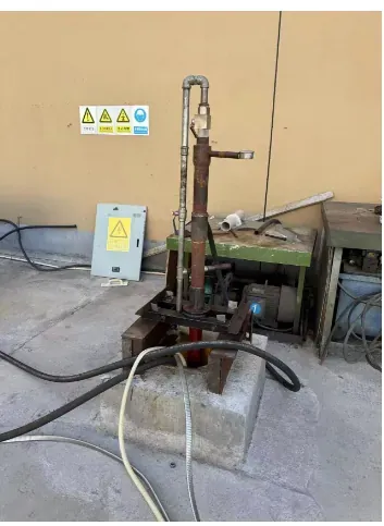
The drive chosen for the 37 kW linear motor was a YDS8045 T4 N. Two commissioning conditions shaped the work. The first was the cable: at this installation the drive and the motor are 1,500 m apart, which is far beyond the length at which the switching pulses from a drive start to stress motor insulation and radiate interference. An output reactor between drive and motor was required, and the parameters were set accordingly. The second was the sequence — the drive was first run with the automatic logic and no load to confirm that the control sequence behaved correctly, and then run loaded, where the pump reached the pressure the customer required.
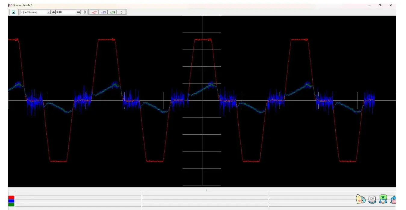
The recorded position, speed and current waveforms from the loaded run confirm the drive is controlling the linear motor as intended. The builder's plan is to test in the factory and then release units in small batches to end users in large oilfields, where borehole pressure and flow sensors would feed back into the drive so that motor power and motion profile adapt well by well. That is the direction this application is heading: not just a different motor, but per-well optimisation of a machine that previously ran to one fixed mechanical rhythm.
Project data
- Drive
- YDS8045 T4 N
- Motor
- 37 kW linear motor
- Cable run
- 1,500 m between drive and motor, with output reactor
- Claimed advantage
- System efficiency said to exceed 30 % against a beam pump's typical 25 %
Project photographs
Industry guide for this application
This project sits in the Oil & Gas Extraction section. The guide covers the duty profile, the machinery and the selection rules for that industry.
Read the Oil & Gas Extraction guide