

Industry selection guide
VFD for Oil & Gas Extraction
Wellhead equipment runs unattended, far from a substation, in weather nobody chooses. This guide covers the variable frequency drive (VFD) decisions that keep production running with nobody on site.
How this industry uses a drive
Oil and gas extraction is an unattended-duty application. A beam pumping unit or a progressive cavity pump may run continuously for months with a visit every week or two, and it does so on a supply that is often the weakest on the network. Everything about the electrical specification follows from that: the drive has to start a load it cannot see, protect a motor nobody is watching, and survive the supply it is given rather than the supply it would like.
The other distinguishing feature is the torque profile. A sucker-rod pumping unit is not a constant-torque load — it is a counterweighted, reciprocating load whose torque swings through a full cycle on every stroke, and whose balance changes as the well conditions change. A drive that treats it as a simple variable-torque load will be oversized on average and still trip on the peaks, and it will miss the most valuable thing the drive can do here, which is to trim the stroke speed to what the reservoir is actually delivering.


Cyclic loads need a torque-aware drive
On a pumping unit, the motor is alternately driven by the load and driving it, twice per revolution. During the upstroke the motor draws power to lift the rod string and the fluid; during the downstroke the counterweight returns energy, and if there is no path for it the DC link voltage rises until the drive trips on overvoltage. This is why pumping units are the classic application for a braking resistor, and why sizing that resistor from the average power figure is a mistake.
The correct approach is to record the actual power cycle — the peak regeneration, its duration and how often it repeats — and size the chopper and resistor from that. Where several wells are grouped into one pad or one electrical house, a shared DC bus lets the regenerating wells feed the lifting ones, which usually removes the resistor entirely and reduces the total installed drive rating.
Below the electrical sizing sits a geological one. A well that was designed for a fixed stroke rate rarely produces best at that rate. Speed control lets the operator slow the pump until it stops pumping off and speed it up until inflow allows, which raises the daily output and reduces the mechanical wear that comes from running a pump partially filled. This is often the business case, with the energy saving as a secondary benefit.
Weak grids, long cables and field power
A well pad at the end of a rural feeder has a short-circuit capacity low enough that starting a large motor directly makes the lights dip across the neighbourhood. A drive fixes that, but it also has to cope with the consequence: the same weak supply produces voltage unbalance and dips that a drive with a tight undervoltage trip will not tolerate. Setting the trip point, adding input reactors and, where the supply is genuinely poor, an active front end, are the usual defences.
Cable length is the other field problem. The distance from the electrical house to the wellhead can easily exceed what a standard drive can feed without reflected-wave overvoltage at the motor terminals, which damages insulation over time rather than immediately. An output dv/dt filter or a sine filter is the answer, and the choice depends on the cable length and the motor insulation class rather than on preference.
Finally, all of this has to be maintainable by a technician who visits the site occasionally. That means parameter sets that can be uploaded and cloned from one well to the next, faults that record what was happening rather than only that something happened, and a control interface that the operator already knows. A drive with a good fault trace saves more field time than a drive with a higher headline efficiency.
Machinery typically driven
- Beam pumping units and sucker-rod pumps
- Progressive cavity and screw pumps
- Linear-motor and long-stroke pumping systems
- Water-injection and disposal pumps
- Crude transfer and booster pumps
- Gas compression and blower units
- Wellhead and separator control skids
Selection rules to apply
- Record the real power cycle on the well before sizing the drive; average power is the wrong number for a reciprocating load.
- Check the drive's braking chopper duty against the regeneration peaks, or plan for a shared DC bus across the pad.
- Add an input reactor where the supply is weak, and review the undervoltage trip setting against measured dips.
- Above the published cable limit, fit a dv/dt or sine filter — reflected-wave overvoltage destroys motor insulation slowly.
- Ask for hazardous-area certification where the drive sits inside a classified zone; a standard enclosure cannot simply be placed there.
- Confirm that parameter sets can be exported and cloned across units from the same pad.
Series to start from
Confirm the rated current against your motor's full-load current before fixing the model; the frame size follows the overload the machine needs, not the motor nameplate alone.
- YDS8000
- YD5900
- YD3000N-IP54
- YD580
- YDBU
Delivered projects in this industry
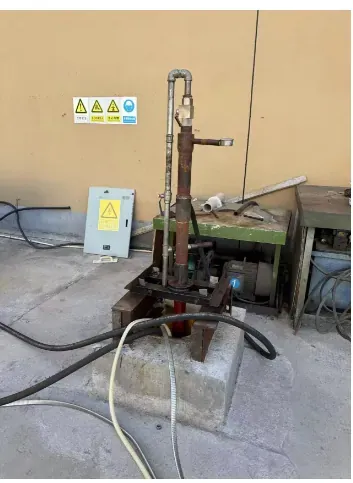
A project record from this industry, with the plant, the motor and the measured result.
Related downloads
Manuals, brochures and selection guides for the series recommended above are in the download library.
Other industries
 Mining & Mineral ProcessingHoists, conveyors, mills and dewatering on a mine site
 Steelmaking & MetallurgyRolling mills, converters, conveyors and hydraulic power units
 Cranes & HoistingHoist, trolley and travel motions on cranes and lifts
 Petrochemical & ChemicalReactors, agitators, decanters and transfer pumps
 Fluid Power & WaterSupply, drainage, treatment and industrial fluid systems
 HVAC & Temperature ControlChillers, cooling towers, air handling and district systems