
Project location: Xinxiang, Henan, China · By MorZan
Generating from Condensate Pressure at a Fertiliser Plant: Four-Quadrant Drive Returns 80 kW to the Grid
- Plant / customer:
- Fertiliser plant, condensate recovery system
- Published:
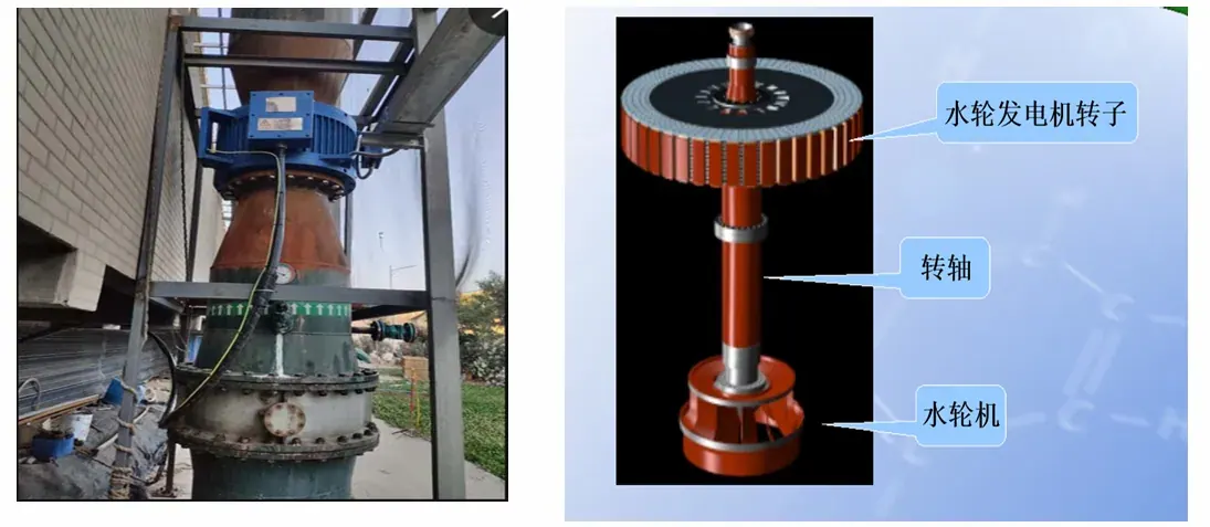
Condensate that leaves a steam system through a trap still holds energy. To move it through the return line the pressure has to exceed what the process and the end user need, and that surplus is usually thrown away as the condensate flashes or throttles. The conventionally simple solution is to let the condensate drive a small impeller on its way through the return pipe — the impeller is coupled to a motor shaft, the flowing condensate resists the impeller, and the motor is turned.
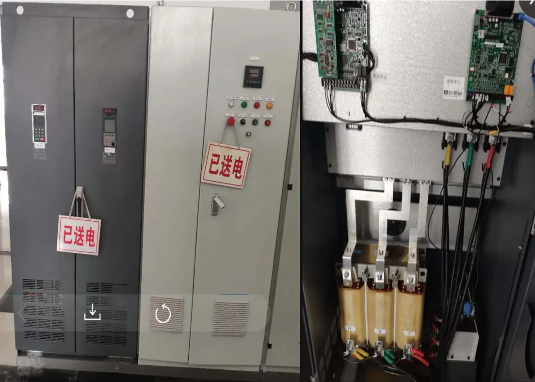
Turning the motor is only half the job. A machine that is spun by the process is a generator, and a generator has to have somewhere to send its power. The engineers at this fertiliser plant in Xinxiang fitted a Yolico four-quadrant drive so that the power has a route back to the supply rather than into a resistor.
The difference between a standard drive and a four-quadrant drive is the direction of energy flow it can accommodate. When the motor is motoring, current flows from the drive to the motor's stator. When the machine is generating, current flows from the stator back into the drive. A four-quadrant unit controls both directions actively and can push the recovered power out to the grid instead of letting the DC bus rise until the drive trips on overvoltage.
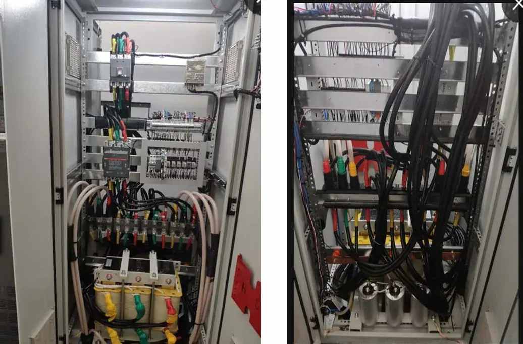
Sizing followed the machine, not the process flow. The motor is rated 132 kW at 750 rpm with a rated current of 194 A and a rated torque of 1,680 N·m, so a 250 A, 132 kW four-quadrant drive was chosen. Two details of the physical layout shaped the installation. The cable run between the electrical room and the water tower motor exceeds 150 m, and long cable runs between a drive and a motor amplify the switching pulses the motor insulation sees, so a sine-wave filter was fitted between drive and motor — with the standard warning that the filter's capacitors must never be connected directly on the drive output side. Because the filter adds inductance to the circuit, its parameters had to be downloaded to the drive board and the relevant parameters changed before it took effect.
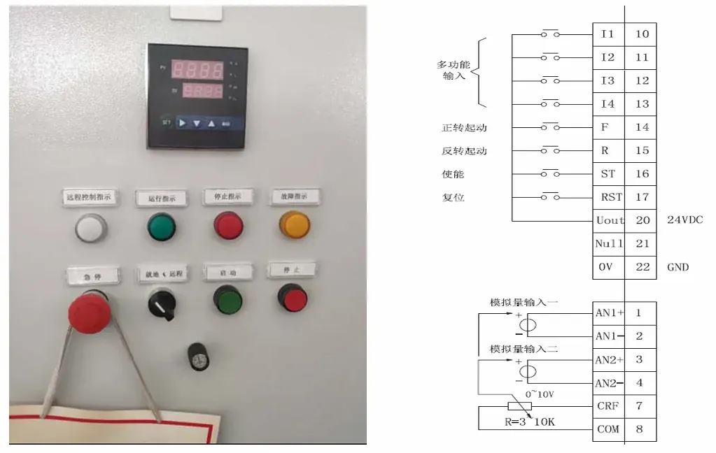
Commissioning was done without the filter first, with no load on the shaft, so the motor parameters were learned cleanly; the analogue inputs were then set up for local and remote control, with channel 1 on a local potentiometer and channel 2 on a remote 4–20 mA signal, switched by closing terminal I1 to common. On site the drive's effective power reads negative while generating, which is the confirming indication that energy is leaving the motor — and the filter's coils run hot because of the current through them. Since the panel was bolted to other cabinets and could not take fans on both sides, cooling was added at the top of the enclosure; 30 °C inside the cabinet with the coils around 70 °C is normal for this arrangement. With a 10 m head and 4,000–5,000 m³/h of condensate flow, the meter upstream of the incoming supply shows the drive group exporting 80–90 kW, which over a 300-day year is on the order of 600,000 kWh generated rather than wasted.
Project data
- Drive
- Four-quadrant, 132 kW, 250 A, with sine-wave filter
- Motor
- 750 rpm PMSM, 194 A, 1,680 N·m
- Cable run
- Over 150 m between electrical room and water tower
- Generation
- 80–90 kW returned to the grid; ≈600,000 kWh per 300-day year
Project photographs
Industry guide for this application
This project sits in the Fluid Power & Water section. The guide covers the duty profile, the machinery and the selection rules for that industry.
Read the Fluid Power & Water guide