
Project location: Limestone quarry, Arequipa Region, Peru · By MorZan
VFD for a Belt Conveyor, and the Braking Nobody Budgeted For
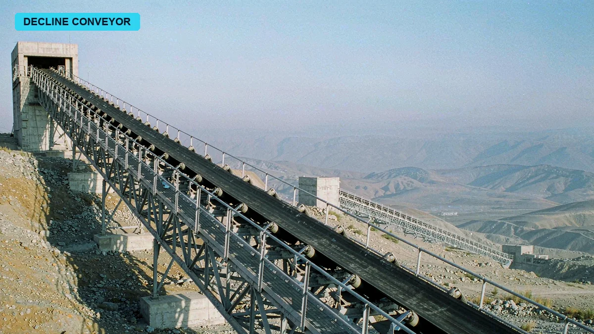
- Plant / customer:
- Cement plant, 5,000 t/day clinker, two 315 kW conveyor drives
- Published:
Three Identical Urgent Emails About One Decline Conveyor
Eight forty in the office. Three unread messages, all with the same subject.
URGENT CONVEYOR TRIP
Same sender each time, Diego plus a string of Spanish surnames, on the domain of a cement plant in Peru.
My first thought was the network. When a mail server retries, it fires several copies in a row, timestamps almost touching, bodies identical to the character.
I opened them and looked at the times. Seven forty last night, seven forty two, seven forty four.
Two minutes apart. A server does not retry every two minutes. A man did this. He hit send, saw nothing happen, hit it again, then once more.
Lima is thirteen hours behind Beijing. For him it was early evening, the day shift had just handed over, nobody had left the gate yet.
Six lines of English in the body, all short, grammar wrong in a few places.
A limestone decline conveyor, 1,850 m long, 120 m of drop, 1,500 t/h at normal rate.
Two 315 kW motors, 440 V, 60 Hz.
It trips two or three times a shift, when the belt is loaded, the HMI shows overvoltage.
The same question at the end. Can a VFD fix this, and what size.
Two attachments. One is a motor nameplate, shot square on. One is the HMI, red letters, OVERVOLTAGE, a number underneath, 780.
I blew the nameplate up to fill the screen. 1,785 rpm, class F insulation, IP55, foot mounted, built March 2019.
A 2019 motor on a line that has run for more than a decade means the motors were replaced. The originals were probably burnt. Whoever did the work changed the motors and nothing else.
I looked at those three numbers for a while. 1,850 m, 120 m of drop, 1,500 t/h. For most of the day those two motors are not pulling. They are being pulled.
I sent back three questions. Belt speed. When the idlers were last changed. Whether the brake was mechanical or electrical.
Forty minutes later. Belt speed 3.6 m/s. Half the idlers replaced last year. Brake is mechanical, hydraulic thruster.
1,850 divided by 3.6 is 514 seconds. Eight and a half minutes end to end.
At full load there is nearly ten minutes of stone lying on that belt at any moment.
Eight hours in a shift, three trips, one every two and a half hours or so. When it trips they restart, wait ten minutes, run again. He wrote it without an exclamation mark and without explaining. Like reading out the weather.
I replied that I needed to see the site.
He answered fast. The plant is south of Arequipa, 2,300 m above sea level, forty kilometres from the nearest town, and an outsider needs a week of clearance to get in.
I still have those three emails. I never deleted them.
A Limestone Quarry Conveyor in Southern Peru I Have Never Seen
I have still never met this customer in person.
The man I deal with is Diego, the maintenance manager. He reads English but cannot follow it spoken. Our first voice call ran forty minutes and I understood about a third of it. The rest came as text afterwards. Now we work in text plus voice notes. He speaks Spanish, I read it through a translator, and when a sentence does not parse I screenshot it and ask.
The primary crusher sits at the top of the pit, the cement plant at the bottom. The belt runs from 2,900 m down to 2,780 m, 1,850 m of horizontal travel, average gradient under seven percent.
That gradient does not sound like much.
The problem is that it never lets up. One continuous fall, no flat section anywhere to act as a buffer.
What he sent later was twelve photos. Crusher discharge, head end, fluid coupling, electrical room, three frames along the line, and one handwritten operating log.
The log was blurred. I asked him to shoot it again. He said tomorrow.
Tomorrow he did not. He sent a thirty seven second video instead. The camera starts on the motor, pans to the HMI where the red text is still flashing, then swings down to the floor. The stone is piled almost to the frame. He says nothing. Only wind noise.
A Decline Conveyor Is Not a Flat Conveyor With a Slope
My first mistake was treating this as an ordinary conveyor retrofit.
On a flat belt or an uphill belt the motor is always doing work. The drive trims the starting current, makes starts and stops smooth, splits load between motors. I have done those three things many times.
A decline belt is not that.
At full load the weight of the stone pushes the belt along. The belt turns the pulley, the pulley turns the gearbox, the gearbox turns the motor. The rotor is driven past synchronous speed, slip goes negative, and the motor stops being a motor and becomes a generator, feeding power back into the drive.
The rectifier in a standard drive is one way only. It turns AC into DC and will not turn DC back into AC. The power has nowhere to go, so it piles up in the bus capacitors.
The voltage climbs. 620, 680, 720, 780.
Protection operates. The drive trips.
While explaining this I walked into a language trap. In Spanish the gearbox is a reductor, a resistor is a resistencia, and the drive is a variador. In his email he wrote reductor as resistencia. I read it as a problem with a resistor and spent two days chasing it, finding nothing.
The next day he added a line. Not the resistor. The gearbox is making a noise.
Two days gone for nothing.
The Potential Energy Came Out Four Times Larger Than I Expected
1,500 tonnes an hour is 416.7 kilograms a second. A 120 m drop, gravity at 9.81.
416.7 times 9.81 times 120, divided by a thousand. 490 kW.
That is the power released by stone falling from the top of the pit to the bottom. I thought I had made an error and ran it again. No error.
Not all of that 490 comes back as regeneration. Idler drag, belt flexing, friction inside the material, plus the lift on the uphill section, take 370 kW out of the line.
490 minus 370 leaves 120.
Sixty for each motor.
What matters is the nature of that number. It is not a pulse during braking. It is power that exists continuously while the belt is loaded. As long as there is stone on the belt and a drop under it, 120 kW keeps flowing backwards.
I wrote one sentence in the proposal. That sentence decided every choice after it.
This is not braking. This is generation.
The First Time I Read Overvoltage as Overload
Before I worked that out I spent three days wrong.
The HMI was flashing OVERVOLTAGE. What the crew told Diego was that the motors were overheating. The casings were too hot to touch and the thermal overload had tripped twice.
So I chased overload. Load factor. Fluid coupling fill. Seized idlers. Belt tension.
Three days, nothing. At full load each motor drew 490 A against a rated 510 A. There was margin.
On the fourth day I asked him to record current and bus voltage together for the ten minutes before a trip.
An old paper chart recorder. Time on the horizontal axis, two traces.
The current trace was flat. The voltage trace climbed in the final two minutes. At the moment voltage peaked, current actually dropped a little.
The motor was not failing to pull. It was pushing power back out.
I gave him seven or eight checks over those three days. He and two men worked through every one of them for nothing. I admitted it by email. He replied that it was fine, they did not know either.
VFD for a Belt Conveyor Starts With the Load, Not the kW
The first job in sizing is not to calculate power. It is to decide what kind of load you have.
A 315 kW motor on a fan, on a pump, on a belt, does not end up with the same drive. Fans and pumps are variable torque loads. Halve the speed and torque falls to a quarter, so you can size light duty. A belt is constant torque. Torque barely changes from zero speed to full speed, and at the moment of starting you have to break static friction, which takes more torque than running does.
So a belt conveyor has to be sized heavy duty.
The difference is not the kW on the nameplate. It is current margin and overload capability. The same 315 kW frame in light duty may be rated 480 A at the output. Heavy duty has to reach 560 A, hold 150 percent for sixty seconds, and hold 180 percent for three seconds.
Those three seconds are the moment a buried belt starts again.
Diego had two quotations in front of him and asked why the gap was so wide.
I said it sits in three places. The module, where the heavy duty frame is one current class up, with thicker busbar and a bigger heatsink, and that is half the difference. The capacitors, where heavy duty carries more bus capacitance to ride through the starting dip and the regeneration rise, and on this line less capacitance means more overvoltage trips. The protection logic, where heavy duty sets its overload curve for constant torque and light duty sets it for variable torque, so if you get that wrong the motor survives and the drive reports overload first.
I told him the money saved on those three would be paid back the first time the belt buried itself.
He took heavy duty.
Starting Torque and Breakaway Torque, the Two Numbers You Cannot Skip
There is a box on the sizing sheet marked starting torque. Most people write 150 percent and move on.
That box needs two numbers.
One is accelerating torque, the torque needed to bring the belt from standstill to rated speed, calculated from inertia. A long conveyor carries a lot of inertia and needs a generous ramp, otherwise current limiting clamps down and the start turns into a crawl.
The other is breakaway torque, the torque needed at the instant you drag a buried pile back into motion. It can be more than twice rated.
Breakaway torque is the dangerous one. It happens at zero speed, and at zero speed the motor has no self ventilation. The heat stays in the rotor cage.
On this line I set 180 percent, a forty second ramp, S curve.
Where the 4.5 Times Starting Current Comes From
Before the retrofit it was direct on line starting with a fluid coupling.
DOL draws four to seven times rated. This one measured 4.5 times, 2,250 A per motor, close to 4,500 A with both starting together.
A fluid coupling softens the mechanical shock. It does not soften the current.
That current lasts twelve seconds. The substation voltage sags and everything on the same bus flickers with it. Diego said the lights in the plant dim when the belt starts, and that they are used to it.
On a drive the start is 1.2 times, 600 A, over forty seconds.
A quarter of the current, more than twice as long, and less heat. Loss goes with current squared, 1.44 against 20.25, a factor of fourteen, while time only grows by 3.3.
Loss per start drops to under a quarter of what it was.
How Long the S Curve Should Be
Forty seconds is not a guess.
1,850 m at 3.6 m/s takes 514 seconds at full load. Ramp too fast and the head end moves while the tail is still standing, the belt stretches, and the tension wave takes more than ten seconds to travel down and back.
Ramp too slow and the belt spends too long at low speed, where the film between belt and idler is boundary lubrication and wear is worse than in normal running.
Forty seconds is what experience says. Fifteen to break away, fifteen at steady ramp, ten to settle.
The first test run used thirty seconds. You could hear the tail pulley slipping. At forty it went away.
Regenerative Braking on a Decline Conveyor, Resistor or Regenerative Unit
Back to that 120 kW.
My first proposal was a braking unit and a braking resistor. That is the standard answer. The manuals all say so. When bus voltage crosses the threshold the braking unit switches on, dumps the excess into the resistor, and it leaves as heat.
Four days after the proposal went out I recalculated it at my own desk and stopped halfway.
A braking resistor is sized on duty cycle. The power printed in the catalogue is the power at ten percent duty, one minute of work in ten, nine minutes to cool.
This belt is not one minute in ten. Under full load on a decline it regenerates every minute.
120 kW into a resistor designed for ten percent duty is ten times the work it was built for.
By then the panel was already in production.
I messaged Diego and said the braking side had to change.
He asked, change to what.
I said, no resistor. Regenerative.
The Ten Percent Duty Cycle on a Braking Resistor
A catalogue gives a braking resistor two numbers, rated power and short time power. Short time can be five to ten times rated, but only for seconds, or tens of seconds.
That design matches a decelerating stop. A fan comes down from fifty hertz to zero, the inertia empties in ten or fifteen seconds, and the resistor rests.
A decline conveyor is not that. Its energy does not come from inertia, it comes from gravity. As long as there is stone on the belt and a drop under it, the power is there. It disappears when you stop.
So a braking resistor on this line is not braking. It is working as a 120 kW electric furnace.
A resistor bank rated 20 kW at ten percent duty, fed 60 kW continuously, takes its enclosure past 200 °C within fifteen minutes. The elements glow locally and the insulators carbonise.
The question is not whether it fails. It is how long it takes.
A Regenerative Unit Is Not Just One More Module
Going regenerative changes more than one module.
The unit connects to the DC bus and inverts DC back into AC at the same frequency and phase as the grid, feeding it to the incoming side. It needs its own line reactor, it has to synchronise with the grid, and it carries its own protection.
The panel layout changes. A regenerative unit makes about as much heat as the drive itself, so the cooling calculated for one machine is no longer enough. Taller enclosure, higher air volume fans.
The incoming side also needs an EMI filter. A regenerative unit switches at high frequency, and without a filter the comms and instruments on the whole line pick up the noise. In a cement plant this matters more than usual, because the belt scale and the weighfeeder carry millivolt signals.
The cost is close to double two braking units plus resistors.
And the resistor set would have been money thrown away anyway.
Cement Plant Raw Material Handling, Dust and Altitude Both Count
The panel ended up beside the crushing station at 2,300 m.
Altitude affects cooling. The air is thinner, so the same fan speed carries away less heat. Catalogues start derating at 1,000 m, one percent for every hundred metres above that.
At 2,300 m it is thirteen points.
315 kW less thirteen percent leaves 274. You cannot size from that number directly. You work backwards, divide the required power by 0.87, get 362, and round up one frame to 400 kW.
I did not take the 400.
I took the 315 kW heavy duty frame and then checked its actual output at that altitude. A heavy duty frame already carries current margin, and with the enclosure temperature under control the measured derating was seven percent. I had that in writing from the factory, because if the belt could not be pulled on site the responsibility was mine.
Dust is the other problem.
Dust at a limestone crushing station is alkaline. It absorbs moisture and sets into a hard shell on insulation surfaces. That shell conducts.
The enclosure went from IP21 to IP54, with two stage filtration on the intake, a metal screen plus pleated media, and the media changed every three months.
I added anti condensation heaters inside, energised when the drive is stopped, to keep the interior above dew point overnight. Arequipa swings hard between day and night, twenty something in the afternoon and close to zero before dawn. Condensation causes more failures here than dust does.
On the 315 kW Heavy Duty VFD Price List I Missed Three Items
Before the quotation went out I checked power and current three times and enclosure dimensions twice.
What I missed was three other things.
Line reactors. The regenerative units need them, and each has to have its own, not shared with the drive. I had counted one.
The DC bus link between the two panels. The two drives share a bus so they can pass energy to each other, which means the bar has to be sized on total current. I had sized it on one.
Spares. The line is in the mountains, six hours from the nearest city, and a failed fan means a week of waiting. The customer raised it himself later. It was not in my quotation.
Those three items moved the contract value twice.
The first revision annoyed Diego. He said, you have been doing this for years, how do you miss it.
I said, because this line is not wired the way we usually wire. Normally one drive feeds one motor and there is no DC link between them. Here the two have to pass energy back and forth, one generating while the other may be pulling, so the current in that bus changes direction.
He was quiet for a moment and then said, recalculate, and send it when the numbers hold.
On the second quotation I put everything in one table, forty seven lines, each with model, quantity, unit price, remark. The remark column said which items were mandatory and which were optional.
He signed quickly.
A 440V 60Hz VFD Shipped to South America, the Nameplate Broke First
The contract was signed and production took three weeks.
The order said 440 V, 60 Hz. That was right.
What was wrong was the pole count.
The motors in Peru are four pole. At 60 Hz synchronous speed is 1,800 rpm and rated is 1,785. Gearbox ratio 26 to 1, drum diameter one metre, belt speed 3.6 m/s.
When I built the parameter sheet I ran it at 50 Hz out of habit. A four pole motor at 50 Hz is 1,500 synchronous, 1,485 rated. Every ratio and belt speed I derived from that was low.
The drive itself was fine. 440 V 60 Hz is a standard build, DC bus nominal 620 V.
The problem was the factory parameters.
The factory default motor table is filled in at 50 Hz. Run the machine as delivered and the motor is capped at 50 Hz, which puts the belt at 3 m/s.
Output drops straight off a cliff.
At 60 Hz the Belt Speed Was Off by Seventeen Percent
I only remembered to check that number after the goods had shipped.
That evening I pulled the parameter sheet and went down it line by line. When I reached rated frequency and saw fifty, my stomach dropped.
I called the factory and told them to change it to 60 Hz before dispatch, rated speed to 1,785, and the field weakening point with it.
The factory said the crates were already sealed and sitting in the warehouse waiting for the truck.
I said, open them.
Opening, reflashing, sealing again cost two days. Those two days fell on a sailing date, missed the booked vessel, rolled to the next one, and arrived eleven days late.
Eleven days is a long time for a customer who is waiting.
When Diego heard, he asked one question. Will it affect belt speed.
I said no. After the change it is 3.6 m/s.
He said, good.
He never raised the eleven days. I still remember that good. There was no politeness in it. He genuinely only cared about the belt speed.
Three Weeks in Callao, the Panel Sat on the Dock
The panel went by sea from Shanghai to Callao. Thirty four days on the water.
Then twenty one days sitting on the dock.
Not customs duty. Paperwork. Peru requires an energy efficiency registration for imported electrical equipment, which needs a declaration of conformity from the manufacturer, and a Spanish manual. The manual was done ahead of time. The declaration was not.
That document is routine here, five days through the system. It landed on the National Day holiday, the person who stamps it was away, and we waited twelve days.
The panel sat in the terminal and the demurrage ran every day.
Diego stopped the line twice waiting for spares, patching with an old panel from stores. He did not push me. Every three or four days he sent a photo of the dock, the panel standing in the yard under a tarpaulin.
On day twenty one the papers were complete and it cleared.
It reached the plant at four in the afternoon local time. It was drizzling while they unloaded. The forklift set the panel on the concrete pad beside the crushing station, I watched on video and told them to throw a sheet of plastic over it.
On my side it was three in the morning.
Installing a Port Bulk Material Conveyor Panel Through a Phone Camera
Once the panel was in place, the wiring was the part I trusted least.
The line is in the mountains and there is no electrical contractor to hire. Two of Diego's electricians had done low voltage distribution. Neither had built a drive panel.
All I had was a phone.
He held it up, I watched the screen. The signal was poor, the picture froze, and he learned to walk a step and stop for two seconds.
I asked him to start at the back of the panel. Cable entry, earth bar, glands, one at a time.
When he reached the earthing I told him to stop. There was one conductor on the earth bar.
I asked how the enclosure was bonded to the site earth grid.
He said, this one is connected.
I said, that is the door bond. The enclosure needs its own conductor, no smaller than half the phase conductor, run to the nearest electrode.
He did not follow half the phase conductor, so I had him point the camera at the cables and measure with his fingers.
Three attempts before he had it.
The line reactor went in backwards once. A reactor has no direction, but the terminals are positioned for a reason. Reversed, the cable has to take a tight bend, the radius is too small, and the lug carries the strain.
That one I only saw the next day, in a photo.
I circled it, drew a red arrow, sent it back.
He refitted it and sent a photo, asking whether it was right now.
I looked for half a minute and said yes.
In that half minute I was working out angles. The photo was shot from an angle and I could not measure, so I read the bend of the cable backwards.
What remote work can do is catch the obvious mistakes. The small ones stay invisible.
The Night the Braking Resistor Burned Through
Commissioning was set for the third day.
The first two days were no load. Motors uncoupled from the gearboxes, rotation check, frequency reference, emergency stop. All normal.
Day three under load, starting at half, 750 t/h.
The belt ran, bus voltage came up from 620 to 655 and held.
I watched from the other side of the video call and thought we had it.
Day four, full stone, 1,500 t/h.
Ten in the morning, belt at 3.6 m/s, both motors regenerating around 60 kW each, bus at 668.
At ten forty the voltage started climbing.
680, 700, 720.
I called Diego and told him to cut the feed. He was coordinating the crusher and it took two minutes.
At 760 there was a noise inside the panel.
Not an explosion. The sharp crack of metal burning through, audible even through a phone earpiece.
Smoke came out of the vents on the panel roof, white first, then black.
I told him to open the main breaker immediately and not to open the door.
He asked why.
I said there are capacitors in there and they are not discharged.
What the Infrared Thermometer Read
We waited twenty minutes after the breaker was opened, then opened the door.
What burned was the braking resistor bank.
That resistor had been a stopgap. We were waiting for the regenerative units to arrive and the customer wanted the line running. Two banks went into the panel, 20 kW nominal, ten percent duty.
Three elements had parted, the ends molten, a small ball at the tip of each. Two insulators were cracked. The paint on the enclosure had gone from silver grey to dark brown.
Diego ran an infrared thermometer over it and read the numbers out to me.
Resistor enclosure 210 °C. The busbar beside it 135 °C. Air inside the panel 89 °C.
Two hundred and ten.
That temperature was not created by the failure. It was there before the failure. The datasheet for that model gives a maximum surface temperature of 180 °C.
Which means that for some period before it burned through, it had been running over temperature.
He sent a thermal image. The resistor bank was white, the panel walls around it orange red, the whole enclosure like an oven.
I looked at that image for a long time.
The problem was not the quality of the resistor. It was that I had sized its duty wrong.
Continuous Generating Duty, Why It Has to Be a Regenerative Unit
After the resistor burned, the line stopped for nine days.
The regenerative units came by air from China, two of them, with reactors and filters. Four days to Lima, two days to clear, one day up the mountain.
During those nine days I wrote something, twelve pages in Spanish, and had Diego print it and tape it to the wall of the electrical room.
The first page was one sentence.
When a conveyor generates on a decline, it is a source, not a load.
The pages after that explained where the power goes.
Power from the motors is rectified into DC and piles up on the bus. Capacitance is finite, voltage is proportional to charge, and more charge means higher voltage.
There are only two ways to bring the voltage down. Turn it into heat, or send it back to the grid.
The problem with the first is not technical. It is the amount of energy. 120 kW continuous is 2,880 kWh a day, 86,000 kWh a month. That power could go back to the grid. Instead it becomes a hot wind on a mountain.
The second way is the regenerative unit. It inverts DC into AC, follows the grid in phase, follows the grid in frequency, and holds a voltage slightly above the grid so the power flows out.
The key word is continuous. A regenerative unit is designed for continuous duty. Its cooling is matched to one hundred percent load, not ten.
How the Wiring Differs From a Braking Unit
A braking unit takes two conductors, bus positive and negative, plus one to the resistor. It does not connect to the grid, does not synchronise, needs no reactor.
A regenerative unit takes five. Bus positive and negative, plus three phase incoming. The three phase has to match the grid, which means grid voltage sensing, zero crossing detection, and a phase locked loop.
A reactor has to be in series on the incoming side. The switching frequency is several kilohertz, and without it the harmonics go back into the grid and disturb everything else on the same bus.
On the first test we ran without the reactor and the belt scale started jumping.
Not small jumps. Jumps of ten tonnes and more.
With the reactor in, it settled.
What Was Lifting the DC Bus Voltage
The document had one chart. Time on the horizontal axis, bus voltage on the vertical.
The flat part is 620, no energy in or out.
The rising part is regeneration. Voltage climbs to 660, the regenerative unit starts drawing, and the voltage is held down.
Without the unit, this line climbs to 780 and trips.
Diego read it and asked whether raising the overvoltage threshold would stop the trips.
I said, raise the threshold and the capacitors go first.
Bus capacitors are usually rated 450 V, two in series for 620, which leaves under twenty percent margin. 780 is already at the edge. Go past it and they break down.
He did not ask again.
Dual Motor Conveyor Load Sharing, How to Set It
Two motors on one belt. The thing you fear is one working and one loafing.
Before the retrofit they were identical motors with fluid couplings. In theory the load divides itself. In practice the fill differs, and the two currents sat thirty or forty amps apart for years.
After the retrofit each drive carries one motor, and the split has to be done in control.
The method is master and follower. The master runs in speed control at the reference belt speed. The follower runs in torque control, with its torque reference coming from the master over the comms link.
That way the two output torques stay in proportion and neither one grabs.
There is a trap here, and I stepped in it on the fifth day of commissioning.
Master on Speed, Follower on Torque
There are several ways to do master follower. We used torque following.
The master calculates a torque percentage and sends it over CAN or RS485. The follower takes it as its own torque reference. Whatever the master delivers, the follower delivers.
Two things have to be considered.
The gear ratio. If the two ratios differ, the same torque percentage gives different output torque. Both gearboxes on this line are 26 to 1, which saved the trouble.
Comms delay. The reference takes a few milliseconds to a few tens of milliseconds to arrive. A belt is an elastic body, and that delay gets amplified into tension fluctuation.
On the first run the follower lagged the master by forty milliseconds.
Forty milliseconds sounds short, but the belt is moving. In forty milliseconds it travels fourteen centimetres. That fourteen centimetres of tension difference shows up at the tail pulley as the belt swaying side to side.
The Half Day I Blamed the Comms
I changed the comms cycle from twenty milliseconds to five. The sway halved. It did not go away.
The problem turned out not to be the comms. It was the filter.
The follower's torque reference had a first order filter with a two hundred millisecond time constant. It was there to reject noise, and it was also dragging the response out.
At fifty milliseconds the sway stopped.
I spent that half day suspecting the comms link. The comms link was fine.
A Stop Costs 1,100 Tonnes of Feed, the Real Loss Is Kiln Output
Once the line was running steady, Diego asked me for an energy saving report.
I did not give him one.
I told him the line does not save energy at full load. A belt is a constant torque load. The same tonnage needs the same work. The drive runs at 97 percent efficiency against 93 for DOL with a fluid coupling. That is the whole difference.
He did not follow. He asked, then why change anything.
So I gave him a different account.
Before the retrofit the line plugged eleven times a month, forty five minutes each time. At 1,500 t/h that is 1,125 tonnes of stone not delivered per event. Eleven events, 12,375 tonnes.
That number looks large, but it is not lost production. The stockpile holds material. The belt can stop for forty five minutes and the kiln keeps eating. The loss starts when the stop runs past the buffer.
The stockpile is designed for six hours. Fix it inside six hours and the kiln never notices. Past six hours the level drops to the alarm line and the kiln begins to pull back.
Of those eleven stops, three were buried belts. A buried belt has to be dug out by hand and then test run, seven or eight hours each. On those three, the kiln ran twenty percent down for six hours.
This plant makes 5,000 tonnes of clinker a day. Twenty percent down for six hours is 250 tonnes not made.
Three times, 750 tonnes.
In the first month after the retrofit there was one stop, twenty something minutes, the electricians cleared it and production resumed. The kiln never came down.
750 tonnes a month is 9,000 a year. At twelve dollars a tonne of clinker margin, 108,000 dollars.
The panel, the regenerative units, shipping, clearance and installation came to 55,000 dollars.
Payback a little over six months.
I did the electricity account as well. About 6.5 percent a year, a bit over 16,000 dollars. Against 108,000 it did not deserve its own report.
I drew both accounts side by side on one sheet and sent it.
He wrote back that he was taking that number to the plant manager.
Belt Conveyor VFD Retrofit Kit, the Questions to Ask
The line has been running a little over five months. Two stops, both from large rock in the feed.
I put the whole thing into a checklist for whoever retrofits a decline belt next.
Start with the duty. Length, belt width, belt speed, inclination, drop. Uphill, flat or decline. How long the decline runs, and whether there is a flat section in it. What the material is, its size, bulk density, moisture.
Then the load. Tonnes per hour. Whether the belt is loaded at start, and how much. Whether it has a history of burying, and how that gets cleared.
Then the motors. How many, what size each, voltage and frequency, pole count, rated current. Encoders or not, and whether they can be added. Whether the gearbox ratios match.
Then the supply. Incoming voltage, frequency, transformer capacity. Whether anything on the same bus is sensitive to harmonics, belt scales, weighfeeders, PLCs. Power factor requirements.
Then braking, and this is the one that matters. Net regenerative power on the decline, and how it was calculated. Continuous or intermittent. If continuous, what rating the regenerative unit is sized at and how the cooling is handled.
Last, service. Altitude, ambient temperature, dust. How spares are supplied, where the nearest service point is. What language the manual has to be in, and what import documents the country requires.
Work through those six groups and the selection will not go far wrong.
315 kW heavy duty, dual drive master follower, energy regeneration. That configuration has run for more than five months with the bus steady between 640 and 660 and not one trip.
The only close call was in September, when an 800 mm rock came through and jammed the crusher opening. The belt was buried for forty minutes. That one was mechanical. The drive held current at the limit and nothing burned.
After that Diego put a grizzly ahead of the crusher.
Plant names, locations and some operating data have been changed to protect the client. The method and the reasoning have not changed, and every figure here can be recalculated with your own numbers.
Project data
- Belt
- 1,850 m decline conveyor, 120 m drop, 1,500 t/h limestone
- Motors
- 2 x 315 kW, 440 V, 60 Hz, 4 pole, 1,785 rpm
- Regenerated power
- 120 kW net continuous, from 490 kW of potential energy
- Drive
- 315 kW heavy duty, master follower pair, regenerative units with line reactors and EMI filters
- Result
- Bus steady at 640 to 660 V, no overvoltage trip in five months
- Payback
- USD 55,000 installed, a little over six months on kiln output
Project photographs
Industry guide for this application
This project sits in the Mining & Mineral Processing section. The guide covers the duty profile, the machinery and the selection rules for that industry.
Read the Mining & Mineral Processing guide