

Industry selection guide
VFD for HVAC & Temperature Control
Cooling is one of the largest electrical loads in a modern building, and almost all of it is variable. This guide explains how a variable frequency drive (VFD) controls it without paying for capacity you are not using.
How this industry uses a drive
A chilled water system spends most of its life at part load. Design day sets the capacity; every other hour of the year the plant is oversized, and the question is only how the surplus is thrown away — by a control valve, by a damper, or by running fewer machines. On a chiller plant where the cooling load follows occupancy and weather, a drive on the condenser and chilled-water pumps and on the cooling tower fans converts that surplus into a speed reduction, and the fan and pump cube laws do the rest.
The complication is that HVAC is a system, not a set of machines. Slowing a pump changes the differential pressure available to the far end of the loop, and the terminal units at the end of the pipe are the ones that suffer. That is why modern chilled water plants are controlled on differential pressure across the most hydraulically remote terminal rather than on a fixed speed, and why commissioning the control loop properly matters more here than in most industries.

Chillers and the condensing side
A chiller's efficiency depends heavily on its condensing temperature, and the condensing temperature depends on how much cooling water is flowing and how cool it is. Running the condenser pumps and the tower fans harder than necessary pushes condensing temperature down and improves the chiller's coefficient of performance, but the pumps and fans then cost more than the chiller saves. There is an optimum, and it moves with the ambient.
That optimum is the reason chiller plants benefit from drives on both sides rather than on one. Controlling the condensing loop on approach temperature — keeping the leaving water a fixed margin above the wet-bulb — turns a fixed-speed pump and fan into a system that tracks the weather. In most buildings the annual saving from the condensing side alone exceeds the cost of converting it.
Evaporative condensers and integrated evaporative units add one more element: a fan, a pump and a water spray that all have to be sequenced. Starting the spray before the fan, and stopping it after, is a sequence rather than a set of interlocks, and a drive that can hold it internally removes a control panel from the roof.
Air handling, fans and filters
A supply fan encounters three different resistances: the ductwork, the dampers and the filter. Only one of them is stable. A filter loads progressively, so the fan has to deliver a constant volume against a rising resistance — which is exactly what a fixed-speed fan cannot do and what a drive running in constant-volume mode can. The saving is real, but the more valuable effect is that the air change rate stays where it was designed to be as the filter loads.
Where the application is return or exhaust air, the fan may already be spinning when the drive is asked to take it over. Flying restart — the ability to synchronise with a coasting motor rather than trip on overcurrent — is what makes a drive usable in a duct system where several fans work in parallel and one may be stopped by a pressure switch at any moment.
Filters and fan coils also raise the pressure-loss question on the water side. When a coil fouls, the flow falls and the terminal is starved; a constant differential-pressure control hides this, and only a flow or temperature measurement at the terminal exposes it. That is a control instrument choice rather than a drive choice, but it is usually the reason a drive retrofit does not deliver the predicted saving.
Noise, harmonics and building interfaces
In a building, the drive has two neighbours that a factory does not have: people and other electronic systems. Acoustic noise at low speed is the first concern. A drive changes its output switching frequency to keep the motor quiet, and on a fan mounted above an office ceiling the difference between a tuned and an untuned carrier frequency is the difference between a complaint and none. Motor noise can also be reduced with an output reactor, at the cost of a slightly larger panel.
Harmonics are the second interface. A building's electrical installation has more sensitive loads per kVA than an industrial one — lifts, IT equipment, laboratory instruments — and a number of harmonics on the distribution board is often written into the electrical specification. Asking for the limit before selecting the rectifier is cheaper than fitting a filter afterwards.
The third interface is the building management system, and it is the one that most often delays a project. The drive has to expose temperature, pressure, flow, power and fault status over the protocol the BMS already speaks, and it has to be possible for the BMS to command a speed as well as read one. Settling that interface — and who writes the point list — before the drives are ordered saves more commissioning time than any parameter setting.
Machinery typically driven
- Centrifugal and screw chillers
- Evaporative condensers and integrated units
- Cooling tower fans
- Chilled and condenser water pumps
- Air handling and fan coil units
- Supply, return and exhaust fans
- District heating and cooling pumps
- Boiler and heat-exchanger circulation pumps
Selection rules to apply
- Control chilled water on differential pressure at the hydraulically most remote terminal, not on pump speed.
- Control the condensing loop on approach temperature: it is the single largest saving in most chiller plants.
- Use constant-volume mode on filter-loaded supply fans instead of a fixed speed.
- Confirm the drive supports flying restart before specifying it on any fan that may be spinning at start command.
- Review carrier frequency and acoustic noise with the client, not after the complaint.
- Agree the BMS protocol and the point list in writing before the drives are ordered.
Series to start from
Confirm the rated current against your motor's full-load current before fixing the model; the frame size follows the overload the machine needs, not the motor nameplate alone.
- Centrifugal-chiller VFD cabinet
- Screw-chiller VFD cabinet
- YD580
- YD287
- YD3000N
Delivered projects in this industry
2 project records from this industry, with the plant, the motor and the measured result.
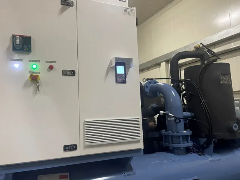 Evaporative-Condenser Chiller Unit: A Liquid-Cooled Drive for a Magnetic-Levitation CompressorPackaged chiller unit, China · 2025-03-22A water-cooled packaged chiller needed a drive that could sit inside the machine and keep a magnetic-levitation compressor stable at every duty point, without the airborne dust a forced-ventilation panel would pull in.
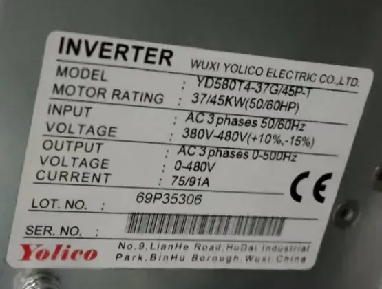 Campus Air-Conditioning Circulating Pump Drive in Yixing: Selection and CommissioningYixing, Jiangsu, China · 2025-09-16A 45 kW chilled-water circulating pump on a university campus runs on a YD580T4-37G/45P-T with terminal start, analogue frequency reference and separate run and alarm relays. Measured current: 68 A balanced.
Related downloads
Manuals, brochures and selection guides for the series recommended above are in the download library.
Other industries
 Mining & Mineral ProcessingHoists, conveyors, mills and dewatering on a mine site
 Steelmaking & MetallurgyRolling mills, converters, conveyors and hydraulic power units
 Cranes & HoistingHoist, trolley and travel motions on cranes and lifts
 Oil & Gas ExtractionPumping units, linear motors and field power
 Petrochemical & ChemicalReactors, agitators, decanters and transfer pumps
 Fluid Power & WaterSupply, drainage, treatment and industrial fluid systems