
Industry selection guide
VFD for Printing & Packaging Machinery
On a printing or packaging line, the variable frequency drive (VFD) is part of the machine. This guide covers the synchronisation, tension and register accuracy that decide whether the product is saleable.
How this industry uses a drive
A printing press or a packaging machine is a set of shafts that have to stay in a fixed relationship while the line runs at hundreds of metres per minute. The unwind has to feed the web at the same rate the printing sections consume it, the sections have to be phase-locked to each other, and the rewind has to take it up at a tension that does not stretch the substrate or let it wander. Nothing about that is a single-drive problem; it is a multi-drive control problem.
The machine-builder side of this industry has its own priorities. The drive sits inside a cabinet on a machine that will be shipped, installed and commissioned by someone else, so it has to be compact, it has to take a fieldbus rather than a bundle of analogue wires, and it has to arrive pre-parameterised. The specification that matters to the OEM is not the drive's overload capability but its engineering effort: how many hours of the builder's time it costs to make the machine work.

Synchronisation between sections
The relationship between the sections of a press is not a speed ratio in the ordinary sense. The web passes over idlers of different diameters, it stretches slightly under tension, and it slips by a small amount at every nip. What the drive system has to hold is therefore the phase of each section relative to the master, corrected by a register mark or a load cell rather than by a calculated ratio. That makes the drive's speed loop and its correction input two separate things, and conflating them is the most common mistake in retrofit work.
The mechanical arrangement decides how the correction is made. On a line with a dedicated register sensor per section, each section's speed reference is trimmed by its own correction term. On a line with a single tension transducer in a dancer, the correction is applied to the whole web path and the sections stay mechanically coupled in ratio. Retrofitting a drive system means identifying which of these the machine actually is, because the control structure follows from it and cannot be chosen freely.
A shared DC bus is often the economical answer on a line with several sections. Acceleration and deceleration energy transfers between the sections through the common link instead of through individual braking resistors, and each section's drive can be smaller because it no longer has to absorb the whole rewind duty on its own.
Tension control on unwind and rewind
Tension has to be held within a narrow band. Too much and the substrate stretches, the register drifts and the finished reel has a slack core; too little and the web wanders, wrinkles and folds. The diameter changes continuously as the reel unwinds, so the drive's torque reference has to be recalculated from diameter on every revolution if the tension is to stay constant.
There are three ways to control it and each has a different drive requirement. Open-loop torque control calculates the diameter from the line speed and the spindle speed and sets the motor torque from it — cheap, adequate on a stable substrate, and dependent on the drive's torque accuracy. Closed-loop control with a load cell measures tension directly and corrections are exact, at the cost of a transducer and cabling per reel. Dancer control uses a mechanical roller and a position sensor, and is the most forgiving of the three on a stretchy substrate.
In all three cases the drive has to be able to run at very low speed with full torque, or even in torque mode at zero speed when the line is threaded. That is a capability question at specification stage, and it is the reason a general-purpose drive chosen on power is often not the right one for a winder axis.
Panel design for a machine that ships
A machine-builder panel has different constraints from a plant panel. It has to fit inside the footprint the machine designer allocated, it has to reject heat without an external air supply because the customer's plant room may be hotter than the builder's workshop, and it has to be wired in a way that survives transport. That usually means drives mounted side by side in a book-style arrangement with the manufacturer's clearances respected to the millimetre, and a common DC bus bar rather than individual rectifiers.
Fieldbus choice is the other defining decision. A drive that takes the machine's existing bus — whether that is a real-time Ethernet or a CAN-based fieldbus — removes a whole layer of I/O from the panel. On a machine with eight or ten axes, the saving in terminals, cable and panel time is usually larger than any difference in drive price.
The last item is safety. A machine tool or a packaging line normally requires a safe torque removal function, and having it integrated in the drive rather than added with contactors changes the panel size and the risk assessment. It also changes the machine's stopping behaviour, which the safety file has to record.
Machinery typically driven
- Web offset and flexographic presses
- Unwind, rewind and infeed sections
- Dyeing, finishing and textile machinery
- Film and carton converting lines
- Form-fill-seal and packaging machines
- Labelling and coding stations
- Corrugated board production lines
- Logistics conveyors and sorters
Selection rules to apply
- Identify whether the machine is register-corrected section by section or dancer-coupled as a whole before designing the control structure.
- Check that unwind and rewind axes can run at near-zero speed with full torque, or in torque mode at standstill.
- Where the line has three or more sections, evaluate a common DC bus: it shrinks the individual drives and removes most braking resistors.
- Choose the fieldbus the machine already uses, and confirm the drive's profile against the machine controller's.
- Respect the manufacturer's side-by-side mounting clearances — derating a drive in a book arrangement is not optional.
- Confirm the safe torque removal function the machine's risk assessment requires, and record it in the safety file.
Series to start from
Confirm the rated current against your motor's full-load current before fixing the model; the frame size follows the overload the machine needs, not the motor nameplate alone.
- YD580E
- YD580
- YD587
- YD287
- YD201
Delivered projects in this industry
2 project records from this industry, with the plant, the motor and the measured result.
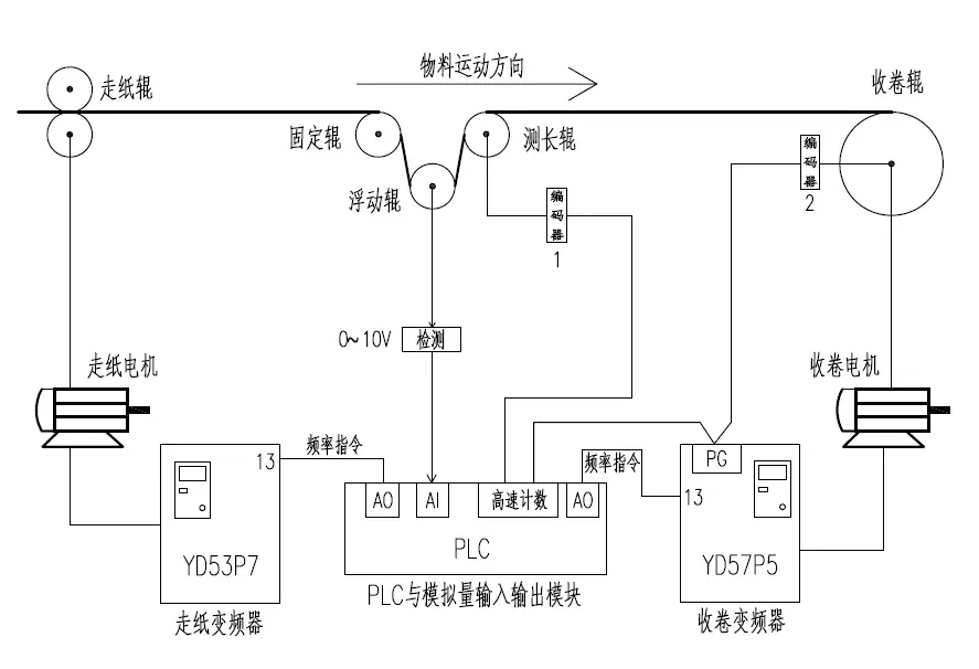 Web Tension Control on a Printing Press: Keeping Rewind Speed Locked to Web SpeedPrinting works, web press · 2025-03-29Paper tension decides whether a printed web comes off flat or creased. This press holds it by synchronising web and rewind speeds, calculating the rewind roll diameter live and trimming the result with a dancer feedback loop.
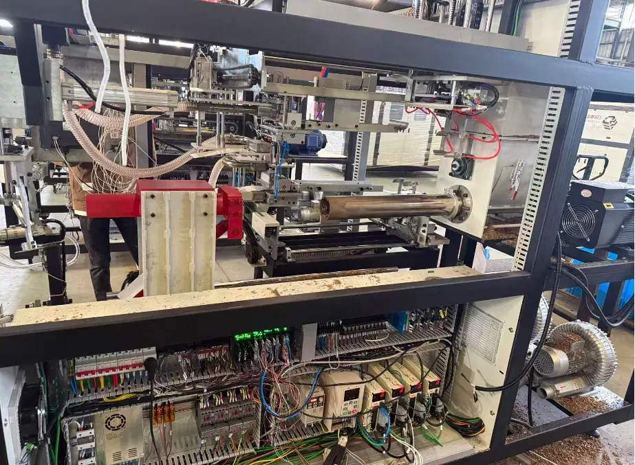 Mushroom Substrate Bagging Machine: Sizing a Drive for Hard Accel and DecelFuzhou, Fujian, China · 2025-12-26A substrate bagger weighs out each bag by counting turns of an auger. The motor reverses constantly and has to accelerate in 0.30 s and stop in 0.10 s, so the 7.5 kW motor is paired with a 25 A drive.
Related downloads
Manuals, brochures and selection guides for the series recommended above are in the download library.
Other industries
 Mining & Mineral ProcessingHoists, conveyors, mills and dewatering on a mine site
 Steelmaking & MetallurgyRolling mills, converters, conveyors and hydraulic power units
 Cranes & HoistingHoist, trolley and travel motions on cranes and lifts
 Oil & Gas ExtractionPumping units, linear motors and field power
 Petrochemical & ChemicalReactors, agitators, decanters and transfer pumps
 Fluid Power & WaterSupply, drainage, treatment and industrial fluid systems