
Industry selection guide
VFD for Robotics & Intelligent Manufacturing
Automation is judged in cycles and microns. This guide covers the variable frequency drive (VFD) and servo characteristics that decide whether a cell holds its accuracy over a full shift and its throughput over a full year.
How this industry uses a drive
Automated machinery separates itself from general industry by one word: repeatability. A packaging machine that runs 5 % slower than another is a minor inconvenience; a machining cell that drifts by a hundredth of a millimetre over a shift is scrap. That is why drives in this sector are judged on bandwidth, position accuracy and the ability to stay in step with a controller rather than on efficiency.
The interesting engineering is in the applications that sit between a standard drive and a true servo. A press, an extruder or a large vibrating table needs high starting torque and precise cycle timing but not micron positioning; a winder needs torque accuracy but not a following-error specification in encoder counts. These duties are served by high-performance vector drives with encoder feedback and a real-time bus, which cost a fraction of a servo system and are far more tolerant of a heavy, dirty load.

When a vector drive is enough and when it is not
The dividing line is whether the load has to follow a position command. A drive in speed or torque mode with encoder feedback will hold a speed ratio to better than a tenth of a percent, which is ample for a conveyor, a winder or a pump. The moment a machine has to move to a coordinate and stop there — a shuttle table, a press with a programmed stroke, a gantry that must return to the same point every cycle — the requirement becomes positional and a servo loop is the honest answer.
Many machines live on both sides of that line at once. A vibro-compacting press for engineered stone, for example, has a main drive that must run at a controlled speed and a mould-filling system that must index to a position; a filling line has a servo indexer and several vector-driven pumps. Specifying the two correctly, rather than putting servo drives everywhere or vector drives where they cannot deliver, is where the cost of a cell is decided.
There is a third category that is often misread: linear motors. A linear motor is a servo without the mechanical transmission, so it removes backlash and screw wear but demands exactly the same positioning loop and a bigger electrical supply than the rotary equivalent. Commissioning one is a control exercise — the encoder scale, the commutation offset and the travel limits all have to be established before anything is allowed to move, and the axis has to be tested at low speed with limited travel first.
Cycle time, torque and the drive's own limits
A machine that runs one cycle every eight seconds has a duty cycle, and the drive has to be specified against that rather than against a continuous rating. A press that draws 200 % of rated current for 1.5 seconds in an eight-second cycle is well inside a heavy-duty drive's overload curve, but the same drive seen on a catalogue continuous rating would look three sizes too large. Getting this right is the difference between overpaying for the panel and replacing a drive every summer.
Thermal management inside the machine follows the same logic. A drive rated for 50 °C in free air, mounted side by side with seven others in a sealed enclosure, will not deliver its nameplate current — and the enclosure's air conditioning load is part of the machine's electrical design, not an afterthought. Machine builders who model this at design stage routinely fit smaller panels than those who add fans until the alarms stop.
On the motor side, the same question appears as thermal margin. A servo motor selected purely on peak torque and mounted in a cell where the ambient is 45 °C will derate; the winding has a thermal time constant and the drive's protection model has to match the motor's actual rating, not its catalogue one. Recording the motor's temperature sensor through the drive, and alarming on it, is the cheapest reliability improvement available on an automated cell.
Integration, diagnostics and the network
An automated cell is a network before it is a set of drives. The real-time bus carries the cycle, the safety signal and often the diagnostic data, and the drive's behaviour during a fault is part of the machine's availability. A drive that can be configured and diagnosed over the same cable that commands it removes a service visit; one that needs a laptop on the machine tool every time a parameter changes does the opposite.
Diagnostic depth is the second integration question. On a cell producing several thousand parts a shift, the useful data is not a fault code but the trend behind it: following error over time, DC link ripple as an indication of capacitor ageing, motor temperature against load. A drive that logs these and exposes them to the machine controller turns maintenance from reactive to planned.
The last point is the operator interface. Much of the installed base in this sector is older machinery being given a new control layer, and the retrofit only works if the people running it can still see what they always saw — the cycle, the state, the fault — without learning a new system. Preserving the existing HMI and letting the drives report into it is usually more valuable to the customer than any feature on the drive's own display.
Machinery typically driven
- Vibro-compacting and forming presses
- Machine tools and spindle drives
- Injection moulding machines
- Pick-and-place and packaging robots
- Linear-motor axes and gantries
- Indexing tables and shuttle systems
- Automated assembly and testing cells
- Extruders and dosing systems
Selection rules to apply
- Size the drive from the duty cycle's RMS current, not from its continuous rating — cyclic machinery is routinely over-specified because of this.
- Decide per axis whether it needs position control or only accurate speed; putting servos on speed-only axes is a common and expensive mistake.
- Model the panel's internal temperature at design stage, including the derating of side-by-side mounting.
- Match the drive's motor protection model to the motor's real thermal rating, and use its temperature sensor.
- Choose the real-time bus the machine controller already speaks, and plan how parameters will be commissioned without a laptop on every machine.
- For a linear-motor axis, commission with limited travel at low speed and verify the commutation offset before full-stroke operation.
Series to start from
Confirm the rated current against your motor's full-load current before fixing the model; the frame size follows the overload the machine needs, not the motor nameplate alone.
- YD287
- YD280
- YD280E
- YD180
- YD201
Delivered projects in this industry
2 project records from this industry, with the plant, the motor and the measured result.
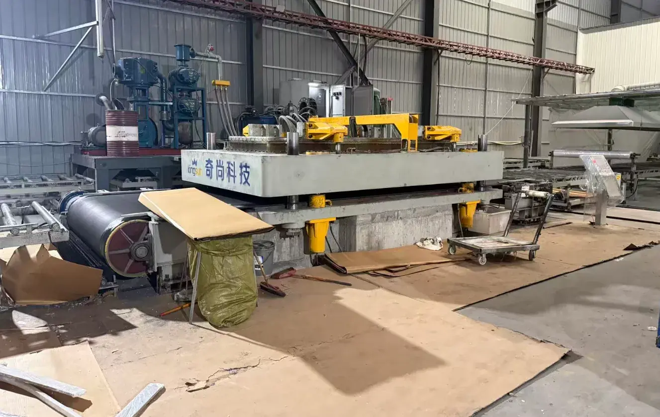 Vibro-Compacting Press for Engineered Quartz Slabs: Drive Selection for a High-Inertia ShakerLinyi, Shandong, China · 2025-12-26Quartz slab presses compact a resin-and-quartz mix with 28–51 Hz vibration under vacuum. The vibration motor has a heavy eccentric load, so drive selection follows starting inertia, not just the 110 kW nameplate.
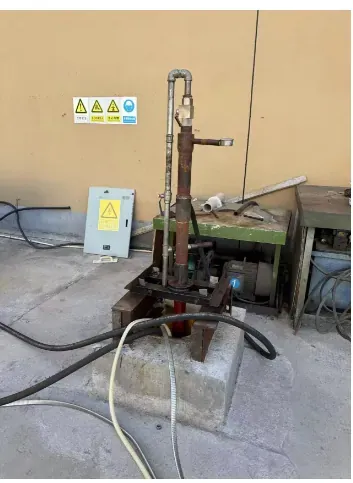 Commissioning a Linear Motor Pumping Unit: Replacing the Beam Pump's Gearbox and CrankShaoxing, Zhejiang, China · 2025-09-16The beam pumping unit is famous for wasting energy in its gearbox and for regenerating on the downstroke. A 37 kW linear motor driven by a YDS8045 removes both problems — and had to be commissioned over a 1,500 m cable.
Related downloads
Manuals, brochures and selection guides for the series recommended above are in the download library.
Other industries
 Mining & Mineral ProcessingHoists, conveyors, mills and dewatering on a mine site
 Steelmaking & MetallurgyRolling mills, converters, conveyors and hydraulic power units
 Cranes & HoistingHoist, trolley and travel motions on cranes and lifts
 Oil & Gas ExtractionPumping units, linear motors and field power
 Petrochemical & ChemicalReactors, agitators, decanters and transfer pumps
 Fluid Power & WaterSupply, drainage, treatment and industrial fluid systems